随着石油、天然气的开采逐渐走向深海,在主管线附近铺设小直径附属管线的背负式管线[1]在深海油田开发中显得日益重要。在背负式管线中,由于小直径附属管线的增设,主管线附近流场会发生较大变化,这种变化对主管线的受力、尾流结构及涡脱频率等都将产生影响。因此,对不等直径串列双圆柱绕流的水动力研究具有一定的工程意义及应用价值。
研究不等直径串列圆柱绕流的方法主要有试验方法和数值模拟方法。Alam & Zhou[2]通过物理试验研究了大圆直径D=25 mm,小圆直径d=(0.24~1.00)D,两圆柱中心间距L=5.5d的双圆柱绕流。结果表明:当d/D减小时,小圆柱的斯特劳哈尔数Sr变小,而大圆柱的Sr数和平均阻力系数增大,升力系数减小。Zhao等[3]用数值模拟方法研究了直径比d/D=0.25,L≤1.175D的双圆柱绕流,结果表明其尾流结构均为单一涡脱落形态。Zhao等[4]进一步数值模拟了Re=50 000,d/D=0.5,L≤1.15D的双圆柱绕流,结果表明涡脱落形态仍为单一形态。Gao等[1]数值模拟了Re=300时不等直径串列双圆柱绕流,发现在不同间距条件下出现了单一涡脱落和双涡旋脱落两种尾流形态。于定勇等[5]数值模拟Re=200时不同直径比、间距比情况下的串列双圆柱绕流,分析了不同直径比及间距比对涡脱落形态、圆柱受力等的影响。
数值模拟方法研究不等直径串列圆柱绕流的关键是求解Navier-Stokes(N-S)方程及其湍流模型,其中大涡模拟方法具有较高的计算精度和较少的计算量逐渐成为数值研究复杂湍流问题的重要方法[6]。由于有限元法具有良好的几何边界和边界条件适应性,而被广泛用于Navier-Stokes(N-S)方程及其湍流模型的求解。但经典的Garlerkin有限元法在处理流体对流占优问题上容易出现数值振荡[7]。为克服该困难,近年来发展了多种有限元法,如Streamline Upwing Petrov-Garlerkin (SUPG)法[8]、Taylor-Garlerkin法[9]、特征线-Garlerkin法[10]。Wang等[11]将Taylor展开引入到特征线-Garlerkin法并结合算子分裂法的优点提出了特征线算子分裂(Characteristic-Based Operator Splitting,CBOS)有限元法。该方法将N-S方程分裂成扩散项和对流项,对流项采用显式格式,显式格式具有单个时间步计算量小、程序易于实现等优点。
本文将大涡模拟方法与CBOS有限元法相结合,数值模拟了Re=1 000的单圆柱绕流。研究Re=1 000时不同直径比、间距比情况下的串列双圆柱绕流,得到不同直径比下的临界间距范围,分析圆柱受力在临界间距范围急剧增大的原因。
1 数值模型 1.1 大涡模拟控制方程采用盒式滤波器[12]对二维非定常无量纲不可压缩流体的N-S方程组进行滤波,根据湍流动能生成与耗散平衡的原则[13],获得以下方程组:
| $\partial {u_i}/\partial {x_i} = 0$ | (1) |
| $\frac{{\partial {u_i}}}{{\partial t}} + {{\bar u}_j}\frac{{\partial {{\bar u}_i}}}{{\partial {x_j}}} = \frac{{\partial \bar p}}{{\partial {x_i}}} + \frac{\partial }{{\partial {x_j}}}\left[ {(\frac{1}{{Re}} + {\upsilon _{\rm{t}}})\left( {\frac{{\partial {u_i}}}{{\partial {x_j}}} + \frac{{\partial {u_j}}}{{\partial {x_i}}}} \right)} \right]$ | (2) |
式中:带“-”的变量为过滤后大尺度变量。i, j=1, 2;(u1,u2)=(u, v),u为水平向速度,v为垂向速度;p为压力;t为时间;(x1, x2)=(x, y),x为水平坐标,y为垂向坐标;雷诺数Re=Ul/υ(其中,U为特征速度,l为特征长度,υ为运动黏性系数)。υt称为亚格子涡黏系数,Smagorinsky[13]对其做出如下假设
| ${\upsilon _{\rm{t}}} = {({c_{\rm{s}}}\mathit{\Delta })^2}\sqrt[2]{{\frac{{\partial {{\bar u}_i}}}{{\partial {x_j}}}\left( {\frac{{\partial {{\bar u}_i}}}{{\partial {x_j}}} + \frac{{\partial {{\bar u}_j}}}{{\partial {x_i}}}} \right)}}$ | (3) |
式中:cs为Smagorinsky系数,一般取0.1~0.2时可获得较好的计算结果,本文取0.1;Δ为网格过滤尺度。
下面的推导过程为求书写简便,略去上横杠“-”。
1.2 CBOS有限元法在每一个时间步内,采用算子分裂法将控制方程(1)和(2)分裂成扩散项和对流项:
| $\left\{ {\begin{array}{*{20}{l}} {\frac{{\partial u_i^{n + \theta }}}{{\partial t}} - (\frac{1}{{Re}} + {\upsilon _{\rm{t}}})\frac{\partial }{{\partial {x_j}}}\left( {\frac{{\partial {u^{n + \theta }}}}{{\partial {x_j}}} + \frac{{\partial u_j^{n + \theta }}}{{\partial {x_i}}}} \right){\rm{ = }} - \frac{{\partial {p^{n + 1}}}}{{\partial {x_i}}}}\\ {\partial u_i^{n + \theta }/\partial {x_i} = 0} \end{array}} \right.$ | (4) |
| $\frac{{\partial u_i^{n + 1}}}{{\partial t}} + u_j^{n + 1}\frac{{\partial u_i^{n + 1}}}{{\partial {x_j}}}$ | (5) |
式中:uin+θ为扩散方程(4)在n+1时刻的解,同时也是对流项方程(5)在n+1时刻的初值;uin+1为对流项在n+1时刻的解,同时也是控制方程式(1)和(2)在n+1时刻的解。
式(4)和(5)应用CBOS有限元法[11],可得如下时间离散形式:
| $\left\{ {\begin{array}{*{20}{l}} {\frac{{\partial u_i^{n + \theta } - u_i^n}}{{\mathit{\Delta }t}} - (\frac{1}{{Re}} + {\upsilon _{\rm{t}}})\frac{\partial }{{\partial {x_j}}}\left( {\frac{{\partial u_i^{n + \theta }}}{{\partial {x_j}}} + \frac{{\partial u_j^{n + \theta }}}{{\partial {x_i}}}} \right){\rm{ = }} - \frac{{\partial {p^{n + 1}}}}{{\partial {x_i}}}}\\ {\partial u_i^{n + \theta }/\partial {x_i} = 0} \end{array}} \right.$ | (6) |
| $u_i^{n + 1} - u_i^{n + \theta } = - \mathit{\Delta }tu_j^{n + \theta }\frac{{\partial u_i^{n + \theta }}}{{\partial {x_j}}} + \frac{{\mathit{\Delta }{t^2}}}{2}u_k^{n + \theta }\frac{\partial }{{\partial {x_k}}}\left( {u_j^{n + \theta }\frac{{\partial u_i^{n + \theta }}}{{\partial {x_j}}}} \right)$ | (7) |
式(7)为对流项(5)沿特征线显式时间离散所得。
对式(6)和(7)采用标准Galerkin加权余量有限元法进行空间离散。基于CBOS有限元的大涡模拟方法求解过程为:①以n时刻的速度场uin作为初值,求解方程(3),得到n+1时刻的亚格子涡黏系数υt;②以n时刻的速度场uin,压力场pn作为初值,求解扩散方程(4),得到n+1时刻速度场的过渡值uin+θ和压力值pn+1;③以uin+θ作为初值,求解对流方程(5),得到n+1时刻速度场uin+1,完成n+1时刻的求解;④转到下一步,重复步骤①~③。

|
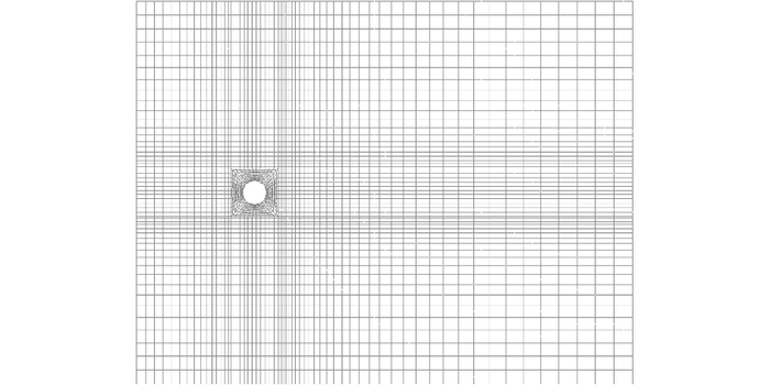
图 1 Re=1 000时单圆柱绕流计算区域网格划分 Figure 1 Computation grids of flow past a single cylinder at Re=1 000 |
如图 1所示,计算域依左中右及上中下划分为9个区域,由于圆柱附近速度、压力等梯度大,对沿柱体径向及围绕柱体四周的网格进行加密,故每个区域的网格尺度各不相同。整个计算域划分为3 238个9节点四边形单元,共有13 212个节点数,其中圆柱表面分布44个网格,88个节点。
2 模型验证 2.1 模型布置计算域尺度在主流方向上取为21D,其中圆柱上游分配5D,横向尺寸为16D,圆柱直径D=0.1为特征长度;入口处指定沿水平方向的均匀来流U=1为特征速度,垂向速度V=0,Re=1 000。为保证圆柱后方涡旋能够顺利通过出口边界,出口处为对流边界∂ui/∂t+∂ui/∂x=0,指定右上角和右下角相对压力p=0;侧壁采用可滑移边界条件;圆柱表面为不可滑移边界条件。
2.2 特征参数表 1列出了计算的平均阻力系数Cd,升力系数CLA及斯特劳哈尔数Sr与已有文献结果的比较。由表 1可见,计算结果与文献结果接近,验证了该模型计算圆柱绕流的有效性。图 2展示了1个周期内5个典型时刻的流线图,从图中可以看出,涡旋交替从圆柱后方产生、发展并脱落,形成卡门涡街。
| 表 1 计算的Cd,CLA及Sr与其他文献数据的比较 Table 1 Comparison between calculated results with data given by other references at Re=1 000 |

|
图 2 Re=1 000时单圆柱绕流1个周期内流线 Figure 2 Streamline of flow past a single cyliner during a cycle at Re=1 000 |
图 3(a)给出了串列双圆柱绕流计算域:上游圆柱直径D=0.1为特征长度,d为下游圆柱直径。流场入口距上游圆柱中心5D,出口距下游圆柱中心16D,横向尺寸为16D,两圆柱中心间距为L。取入口处水平方向的均匀来流U=1为特征速度,垂向速度V=0,Re=1 000,指定右上角和右下角相对压力p=0;出口处为对流边界∂ui/∂t+∂ui/∂x=0;侧壁采用可滑移边界条件;两圆柱表面为不可滑移边界条件。

|
图 3 不等直径串列双圆柱模型布置及网格划分 Figure 3 Computational domain and grid divison when d=0.2D and L=1.75D |
计算了d/D=0.2,0.4,0.6,0.8,L/D=1.75,1.8,1.9,2.0,2.1,2.2,2.25,2.5共计32种工况。图 3(b)给出了d/D=0.2,L/D=1.75时局部网格划分情况,计算域依左中右及上中下划分为12个区域,对柱体径向及围绕柱体四周的网格进行加密,每个区域的网格尺度各不相同。整个计算域划分为4 604个9节点四边形单元,共有18 717个节点数,其中两圆柱表面均分布40个网格,80个节点。
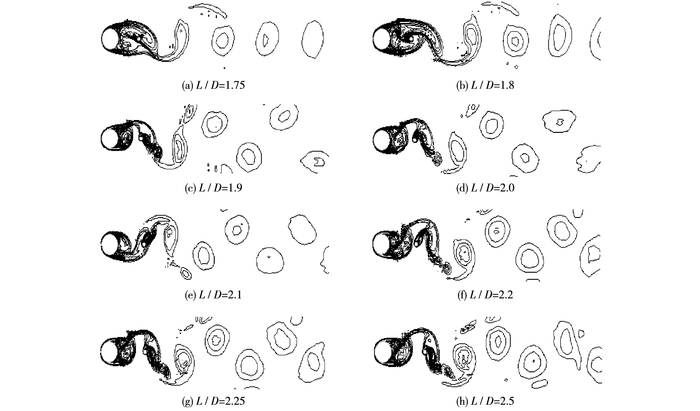
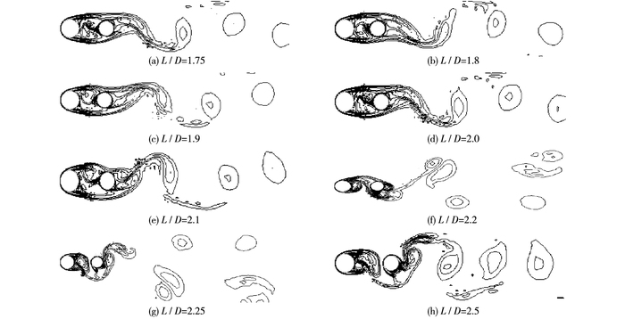
3.2 尾流形态分别计算了直径比d/D为0.2,0.4,0.6,0.8时在不同间距比下的涡量等值线分布,为节约版面,只给出d/D=0.2和d/D=0.6时的涡量等值线分布(见图 4和图 5),计算结果表明,d/D=0.2时,L/D≤1.8时上游大直径圆柱分离的剪切层附着在下游小直径圆柱表面,涡旋脱落仅发生在下游圆柱后方,呈现单一涡脱落,涡脱落位置离下游圆柱较远;当L/D≥1.9时,上游大圆柱及下游小圆柱均产生涡旋脱落,呈现双涡旋脱落形态,涡脱落位置较L/D≤1.8时更靠近下游圆柱。当d/D=0.4,0.6,0.8时,L/D≤2.1时上游圆柱后方无涡脱落呈现单一涡脱落形态;L/D≥2.2时呈现出双涡旋脱落流态。L/D≥2.2时涡脱落位置离下游圆柱距离大于L/D≤2.1时的距离。

|
图 4 d/D=0.2时不同间距比下的涡量等值线 Figure 4 Vorticity contours with different spaces when d/D=0.2 |

|
图 5 d/D=0.6时不同间距比下的涡量等值线 Figure 5 Vorticity contours with different spaces when d/D=0.6 |
图 6和7分别给出了在不同d/D情况下上、下游圆柱平均阻力系数及升力系数随L/D的变化曲线。由图可知,d/D=0.2时,上、下游圆柱平均阻力系数及升力系数在L/D=1.8~1.9时急剧增大;d/D=0.4,0.6,0.8时,在L/D=2.1~2.2急剧增大。结合图 4~5流场尾流结构表明:d/D=0.2时临界间距范围为1.8D~1.9D;d/D=0.4,0.6,0.8时其临界间距范围为2.1D~2.2D。

|
图 6 上游圆柱升、阻力系数随L/D的变化曲线 Figure 6 Lift and drag coefficients of upper cylinder under different L/D |

|
图 7 下游圆柱升、阻力系数随L/D的变化曲线 Figure 7 Lift and drag coefficients of lower cylinder under different L/D |
图 8和9分别给出了d/D=0.2,0.4时在临界间距区间约1个周期内不同时刻的压力分布云图。从图 8(a)和9(a)可以看出:两圆柱间隙处压力较稳定,上游圆柱上、下表面压力接近,故其升力系数比单圆柱绕流小很多。同时间隙处压力低于下游圆柱近尾流区,故下游圆柱平均阻力系数为负值。由于未达到临界间距,涡脱落位置离下游圆柱较远,对其背流面上、下表面的压力差影响较小,故升力系数较单圆柱偏小。

|
图 8 d/D=0.2时临界间距区间的压力分布 Figure 8 Pressure distribution at critical spacing range when d/D=0.2 |

|
图 9 d/D=0.4时临界间距区间的压力分布 Figure 9 Pressure distribution in critical spacing range when d/D=0.4 |
从图 8(b)和9(b)可以看出:达到临界间距后,上游圆柱尾流区上下表面交替出现强负压区,表明有涡旋脱落,故上游圆柱平均阻力系数及升力系数值均增大。下游圆柱迎流面压力相对其尾流区压力显著提高,故下游圆柱平均阻力系数均增大。另外,下游圆柱迎流面上表面正压力逐渐增加(减小),下表面负压力则逐渐减小(增加),这对下游圆柱上下表面压力差产生叠加影响,导致下游圆柱升力系数振幅剧增。
d/D=0.6,0.8时上、下游圆柱平均阻力系数及升力系数急剧变化的原因与d/D=0.2,0.4时相近。两圆柱间距达到临界间距后,圆柱周围压力变化导致其平均阻力系数及升力系数增大。
4 结语将经典Smagorinsky亚格子模型与特征线算子分裂有限元相结合,通过自编程序模拟了Re=1 000的单圆柱绕流,计算结果与现有文献结果吻合较好,验证了本文模型计算圆柱绕流的有效性。研究了Re=1 000,d/D=0.2~0.8,L/D=1.75~2.50的串列双圆柱绕流,得出如下结论:
(1) d/D=0.2时,L/D≤1.8时涡旋脱落仅发生在下游圆柱后方,流场呈现单一涡脱落形态;L/D≥1.9时,两圆柱后方均产生涡旋脱落,流场呈现双涡旋脱落形态;d/D=0.4,0.6,0.8时,L/D≤2.1时流场呈现单一涡脱落形态,L/D≥2.2时呈现双涡旋脱落形态。
(2) d/D=0.2时,上、下游圆柱平均阻力系数及升力系数在L/D=1.8~1.9时急剧增大;d/D=0.2,0.6,0.8时,在L/D=2.1~2.2时急剧增大。
因此,对Re=1 000的不等直径串列双圆柱绕流:当d/D=0.2时,临界间距范围为1.8D~1.9D;当d/D=0.4,0.6,0.8时,其临界间距范围为2.1D~2.2D。
| [1] |
GAO Y Y, STEPHONE E, YU D Y, et al. Flow characteristics behind two unequal circular cylinders in tandem arrangement[J]. International Society of Offshore and Polar Engineers, 2010, 1: 1084-1088. |
| [2] |
AlAM M M, ZHOU Y. Strouhal numbers, forces and flow structures around two tandem cylinders of different diameters[J]. Journal of Fluids & Structures, 2008, 24(4): 505-526. |
| [3] |
ZHAO M, CHENG L, TENG B, et al. Numerical simulation of viscous flow past two circular cylinders of different diameters[J]. Applied Ocean Research, 2005, 27(1): 39-55. DOI:10.1016/j.apor.2004.10.002 |
| [4] |
ZHAO M, CHENG L, TENG B, et al. Hydrodynamic forces on dual cylinders of different diameters in steady currents[J]. Journal of Fluids & Structures, 2007, 23(1): 59-83. |
| [5] |
于定勇, 刘洪超, 王昌海. 不等直径串列双圆柱体绕流的数值模拟[J]. 中国海洋大学学报(自然科学版), 2012, 42(7/8): 160-165. ( YU Dingyong, LIU Hongchao, WANG Changhai. Numerical simulation of viscous flow past two tandem circular cylinders of different diameters[J]. Periodical of Ocean University of China, 2012, 42(7/8): 160-165. (in Chinese)) |
| [6] |
MAHESH K, CONSTANTINESCU G, MOIN P. A numerical method for large-eddy simulation in complex geometries[J]. Journal of Computational Physics, 2004, 197(1): 215-240. DOI:10.1016/j.jcp.2003.11.031 |
| [7] |
HACHEM E, RIVAUX B, KLOCZKO T, et al. Stabilized finite element method for incompressible flows with high Reynolds number[J]. Journal of Computational Physics, 2010, 229(23): 8643-8665. DOI:10.1016/j.jcp.2010.07.030 |
| [8] |
BROOKS A N, HUGHES T J R. Streamline upwind/Petrov-Galerkin formulations for convection dominated flows with particular emphasis on the incompressible Navier-Stokes equations[J]. Computer Methods in Applied Mechanics and Engineering, 1990, 32(1/3): 199-259. |
| [9] |
SELMIN V, DONWA J, QUARTAPLLE L. Finite element methods for nonlinear advection[J]. Computer Methods in Applied Mechanics and Engineering, 1985, 52(1/3): 817-845. |
| [10] |
ZIENKIEWICZ O C, MORGAN K, SAI B V K, et al. A general algorithm for compressible and incompressible flow-Part Ⅱ. Tests on the explicit form[J]. International Journal for Numerical Methods in Fluids, 1995, 20(20): 887-913. |
| [11] |
WANG D G, WANG H J, XIONG J H, et al. Characteristic-based operator-splitting finite element method for Navier-Stokes equations[J]. Science China Technological Sciences, 2011, 54(8): 2157-2166. DOI:10.1007/s11431-011-4444-7 |
| [12] |
SAGAUT P. Large eddy simulation for incompressible flows[M]. Heidelberg: Springer-Verlag, 2002.
|
| [13] |
DENHAM, M K, BRIARD P, PATRICK M A. A directionally-sensitive laser anemometer for velocity measurements in highly turbulent flows[J]. Journal of Physics E: Scientific Instruments, 2001, 8(8): 681-693. |
| [14] |
HU C, KOTERAYAMA W. Numerical study on a two-dimensional circular cylinder with a rigid and an elastic splitter plate in uniform flow[J]. International Journal of Offshore and Polar Engineering, 1994, 4(3): 193-199. |
| [15] |
JESTER W, KALLINDERIS Y. Numerical study of incompressible flow about fixed cylinder pairs[J]. Journal of Fluids and Structures, 2003, 17(4): 561-577. DOI:10.1016/S0889-9746(02)00149-4 |
| [16] |
MITTAL S, KUMAR V, RAGHUVANSHI A. Unsteady incompressible flows past two cylinders in tandem and staggered arrangements[J]. International Journal for Numerical Methods in Fluids, 1997, 25(11): 1315-1344. DOI:10.1002/(ISSN)1097-0363 |
 2017
2017 
